 Virtual Colossus
Overview
This page gives some detail on the parts of Typex, to help you understand how it works. The image below shows the main sections of the machine. It is a Typex Mark 23, which has the same main parts as the Mark II and Mark 22 (Virtual Typex simulates the Mark 22), plus a few additions for fitting the CCM (Combined Cipher Machine) rotor, including the four pillars and the connector at the back behind the right-hand printer.
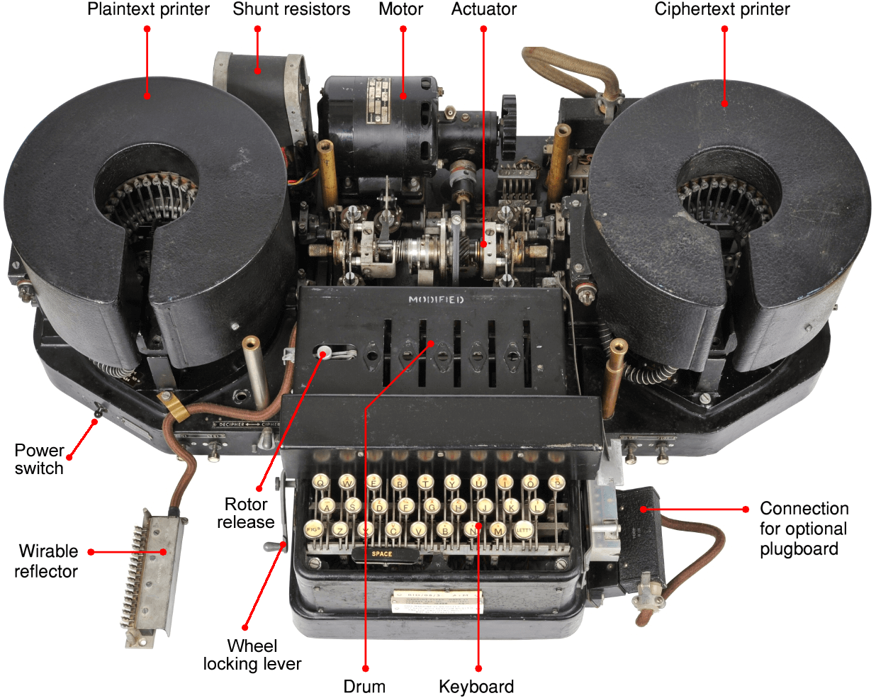
Typex was built on the same principles as Enigma, which allowed it to be compatible with machines like the Enigma I, but later models added a few modifications that increased its security.
These additions came at the cost of weight and size: it was not a portable machine like Enigma, and it needed mains power. The Mark II, for example, weighed around 120 lb (54 kg) and measured about 30 × 22 × 14 inches (760 × 560 × 360 mm).
- Typex has five rotors. The left three move in the same way as Enigma’s; the two on the right can be moved to change the start position, but don’t move during encryption.
- Typex rotors could have more turnover notches (where each rotor turns the next one along) than standard Enigma rotors.
- Later rotors had a removable insert holding the wiring, which could be put back reversed, increasing the possible wiring combinations.
- An optional plugboard allowed each letter to be mapped to any other; Enigma’s only swapped letters in pairs.
- Printers instead of a lampboard meant less chance of mistakes in recording the cipher text.
- It could type numbers and punctuation, and could be connected directly to a teleprinter so messages could be sent straight away.
Rotors
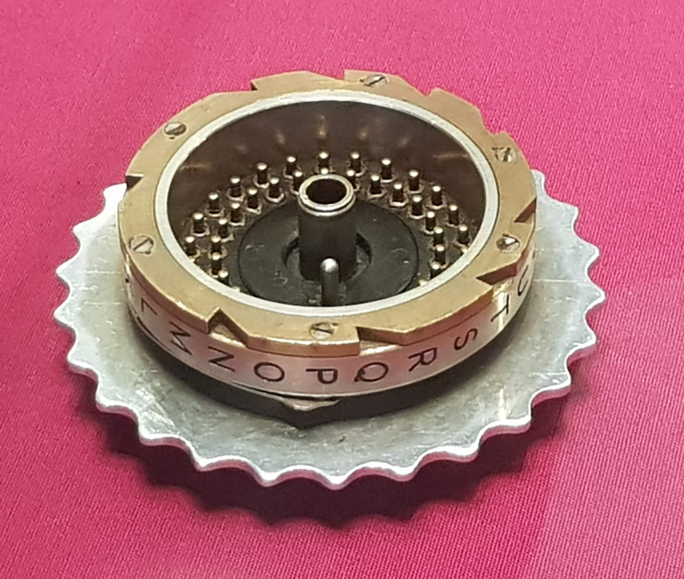
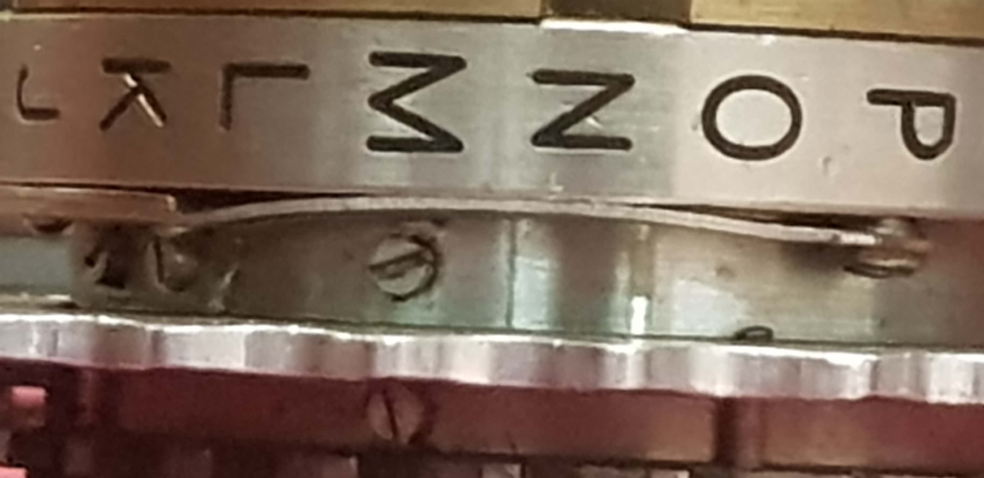
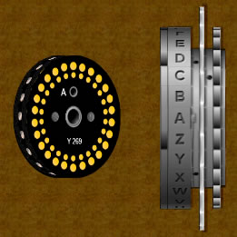
Typex rotors are very similar to Enigma’s, but with two rings of contacts for better reliability.
Each rotor had 26 letters round its edge, each lined up with one of the 26 contacts on either side. The letter wheel and wiring insert could also be turned relative to the input contacts by releasing a spring-loaded pin and turning the body, the equivalent of the Enigma’s Ringstellung (ring setting). Typex rotors could have several notches (5, 7 and 9 were common), each of which, when lined up, turned the next wheel to the left on one step.
The first rotors had fixed wiring cores, but later versions had an insert (or slug) holding the wiring, with contacts on either side. Each rotor body could take several different inserts, which could also be fitted reversed, greatly increasing the number of possible wiring combinations.
The TICOM document ADM 1-27186, “Review of the security of naval codes and cyphers, September 1939 to May 1945”, from the post The secret history of Typex QQQQQ on ciphermysteries.com, gives some information on their use and on a number of changes made to increase security.
It says that in 1939 a set of five “black” rotors was in use by the RAF and the Army. On 1 June 1941, two more “red” drums (from an original set of five) were added, giving seven to choose from.
In February 1943, two more sets of 7 rotors were brought into use by the Navy: “Code X” for normal secure traffic, and “Cypher X” for more secure traffic. From then on, the original set of seven was kept for inter-service traffic only.
Unfortunately, as of January 2020, the official Typex rotor wiring is still classified, so all the rotor wiring in Virtual Typex is either random or copied from other simulations already released (GCHQ CyberChef and Typex, a Windows simulator by Geoff Sullivan).
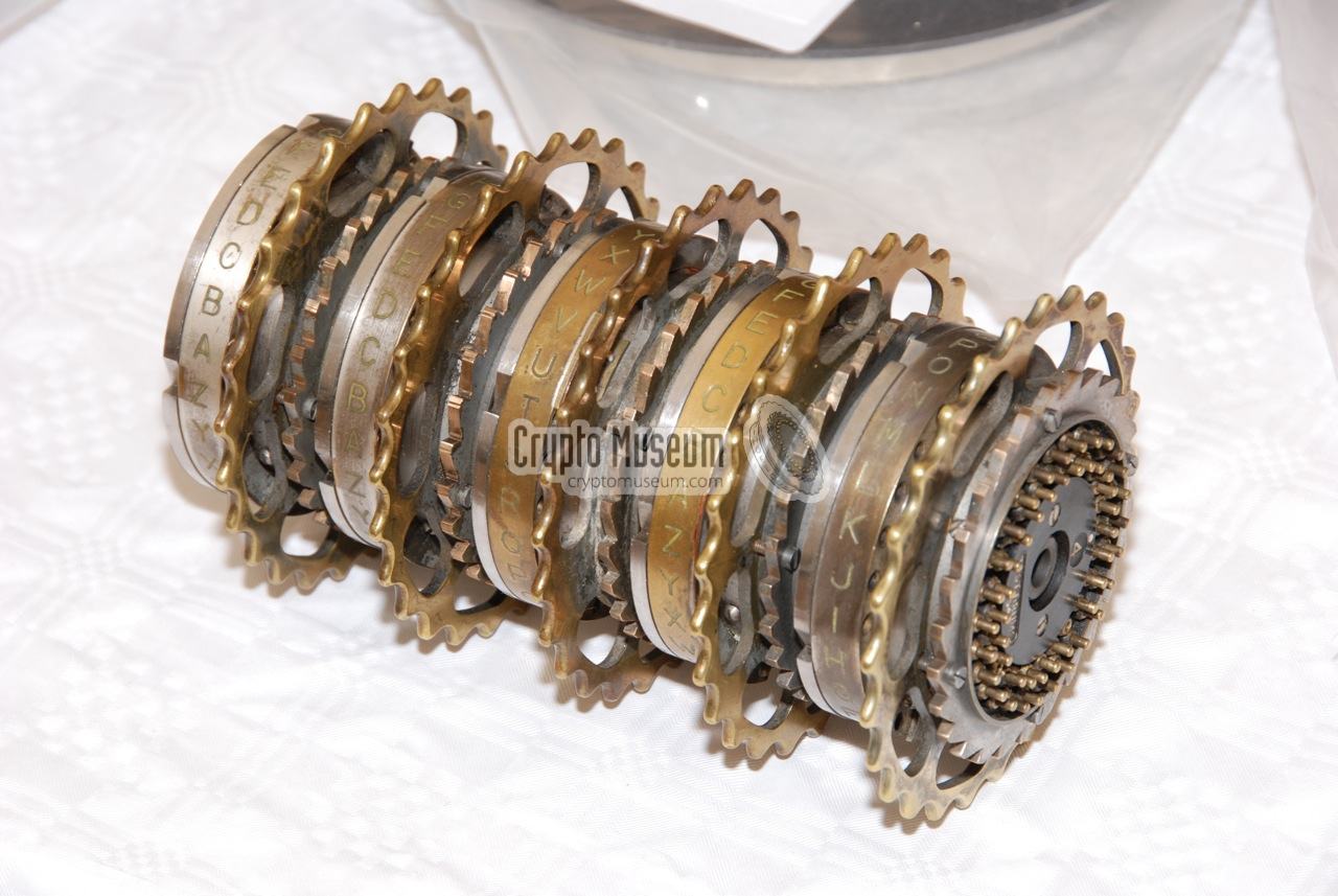
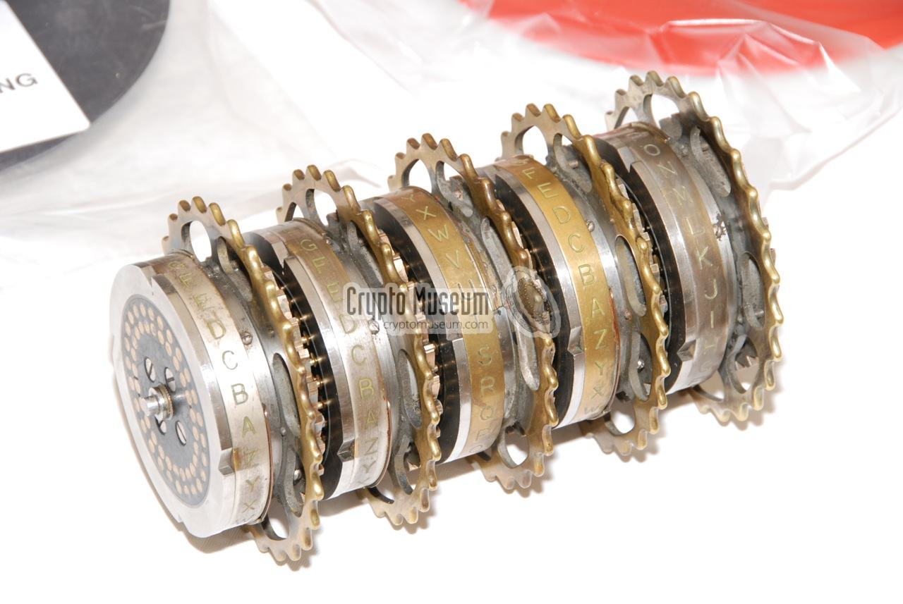
When a Typex needed repair and had to be taken away for maintenance, the live rotors were removed and kept at the secure location. Without five rotors the electrical circuit wouldn’t be complete, so the Typex wouldn’t print or move properly. So engineers used a set of test rotors, like those above, to check the Typex while it was being repaired. These rotors had no removable inserts and appear to have all been wired straight through, with no crossed wires inside.
The drum unit
The drum unit, sometimes called the rotor basket, wiring maze or stepping unit, is the central part of the machine, which does the encryption and decryption of the input letters. It has a bay for five rotors between the input head on the right and the reflector head on the left. The rotors are moved by the pawl bar at the back, which is lifted from behind by a lever attached to the actuator. All five pawls, one per rotor, are lifted together, but the two right-hand ones are held away from their rotors by the brackets shown, so those two rotors stay still.
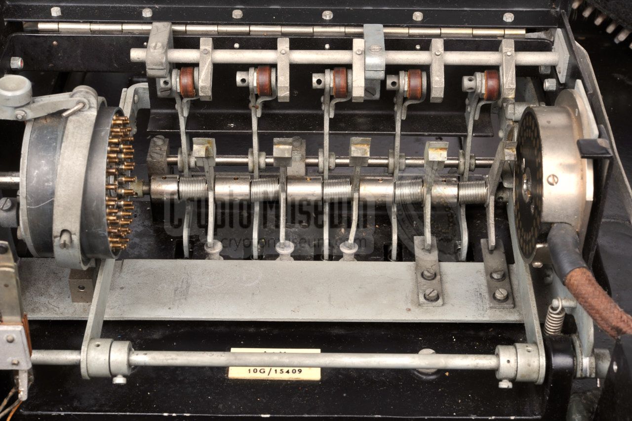
To release the rotors from the drum unit, first open the top cover and lift the wheel locking lever to the left of the keyboard. This brings the rotor set forward and down slightly, away from the red pressure rollers at the top of the picture above. Then press the button on top of the reflector head, which lets the reflector move to the left, releasing the rotors and the axle they are mounted on. (The axle holding the rotors isn’t simulated in Virtual Typex, to make it easier to swap single rotors.)
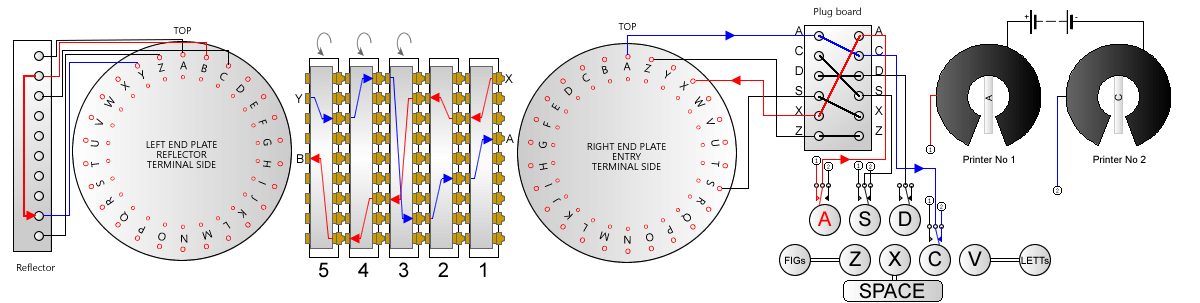
The Typex input wiring is backwards compared with Enigma’s: letters enter the rotors in clockwise order rather than Enigma’s anticlockwise (or the other way round, depending on which side you look from). This is confirmed in notes in GCHQ’s CyberChef Typex library.
The reflector and plugboards
On the original Typex machines up to the Mark 22, the reflector head was a fixed wired connection that couldn’t be removed or rewired. The Mark 22 added the option of two plugboards, one on each side of the keyboard. The left-hand plugboard was wired into the reflector head, so it could be reconnected as needed, either for extra security or to emulate the Enigma machine’s reflectors.
Both plugboards could easily be removed as whole units, allowing a quick swap to a different unit without rewiring each one (for example, to swap between the Enigma A, B and C reflectors).
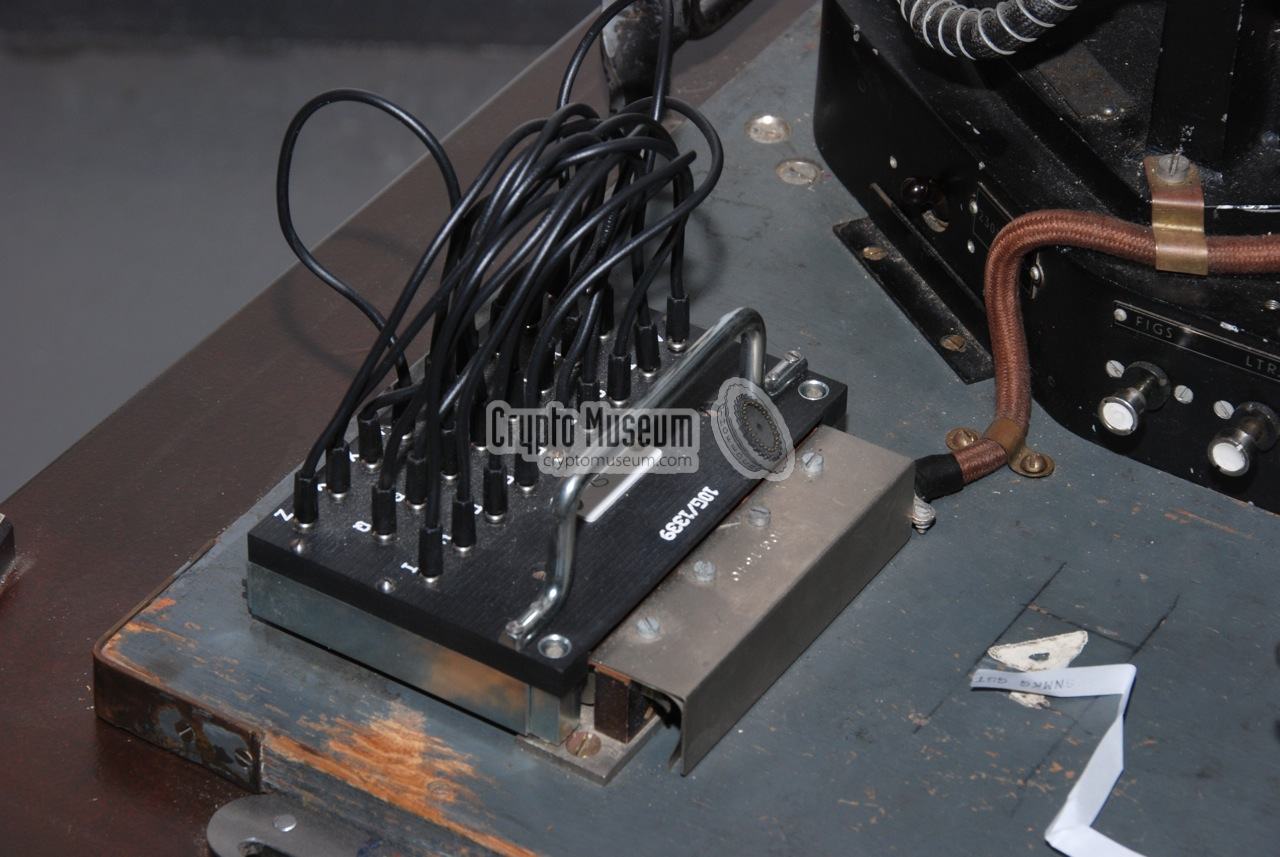
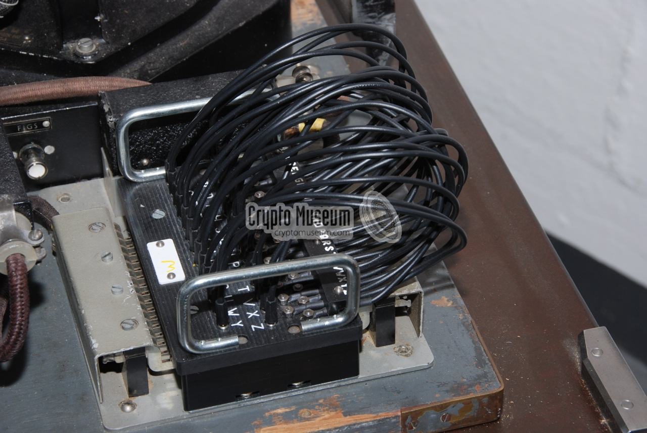
As mentioned above, the right-hand entry head is wired the other way round from Enigma’s, which raises the question of how Typex emulated Enigma. A specific reference to how this was done is hard to find, and it could be done in several ways. I believe the simplest way, without rewiring the Typex head itself (and the way Virtual Typex works), was to use an altered plugboard when deciphering Enigma. This would rewire the letter B from the keyboard to the Z terminal inside the plugboard, C to Y, D to X and so on to Z to B, reversing the effect of the opposite-handed entry rotor. This seems to be agreed by the developers of GCHQ’s CyberChef Typex implementation.
The wiring of the standard Typex reflector has not been officially released, but while searching for documents about Typex, I came across a handwritten document by an engineer who used to repair various models of Typex.
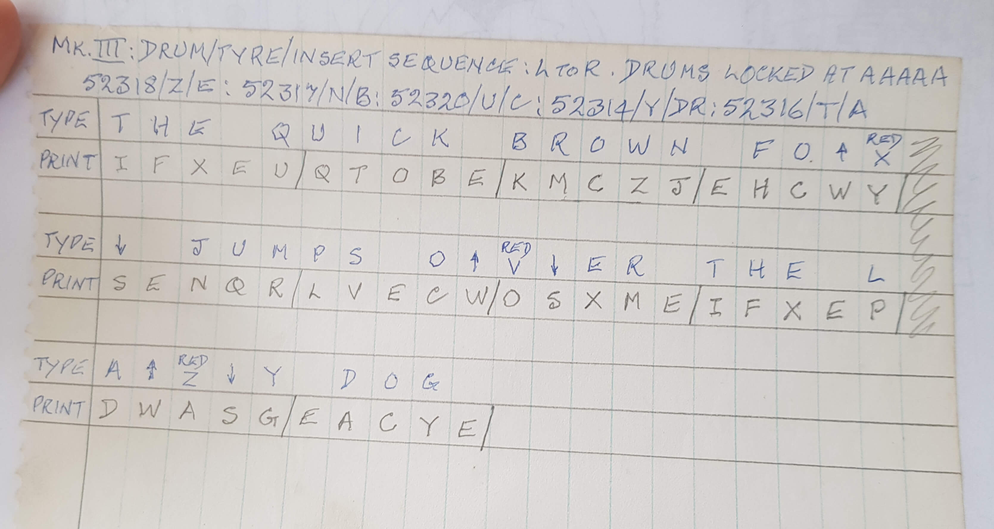
It shows a test message used to check that a cipher machine was working again after repair, and we can see it was used on a Typex Mark III, which had a fixed reflector head and no external plugboard. Look closer and there is something we can learn from it.
All the spaces (which Typex enciphers as the letter X) are shown converting to the letter E. Also, each letter is reciprocal: T enciphers to I, and I back to T. This can only happen if all five rotors are wired straight through, so the reflector wiring can be worked out, as the rotors add nothing to the cipher in this case.
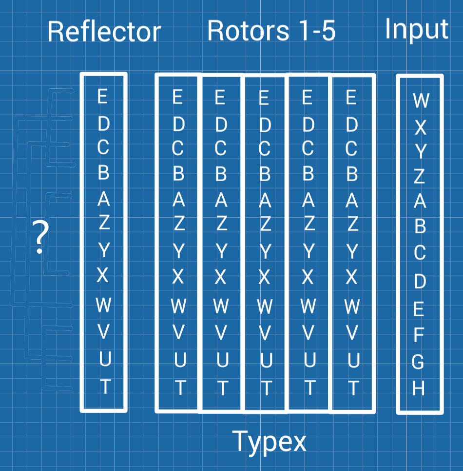
To do this you need one more piece of information: how the input and reflector heads (the connectors on either side of the rotors) are wired. The diagram above shows that on Typex the input was wired reversed relative to the reflector. So while the A input pin lines up with the A reflector pin, B sits opposite Z, C opposite Y, D opposite X, and so on to Z opposite B.
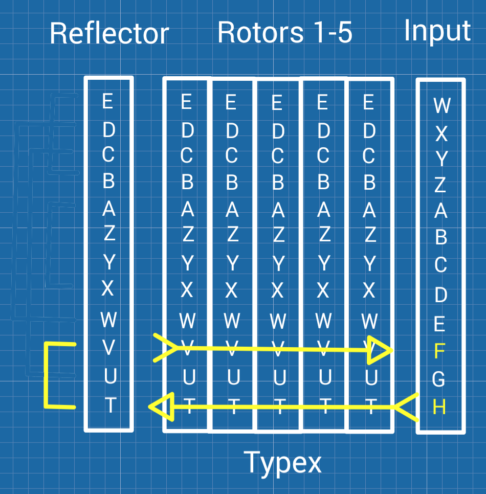
Take the second letter, H, which is enciphered to F, as a first example. Tracing from the H on the input head, straight through all the rotors, we arrive at the T pin on the reflector. To give the result on the document, T must be wired to V on the reflector, as V connects back through the rotors to F. Likewise E connects straight to reflector W, which must be wired to D to give the final letter X. As the engineer kindly used a sentence containing every letter, we can repeat this until we have all 13 connections. So this is what I believe to be the fixed Typex reflector wiring.
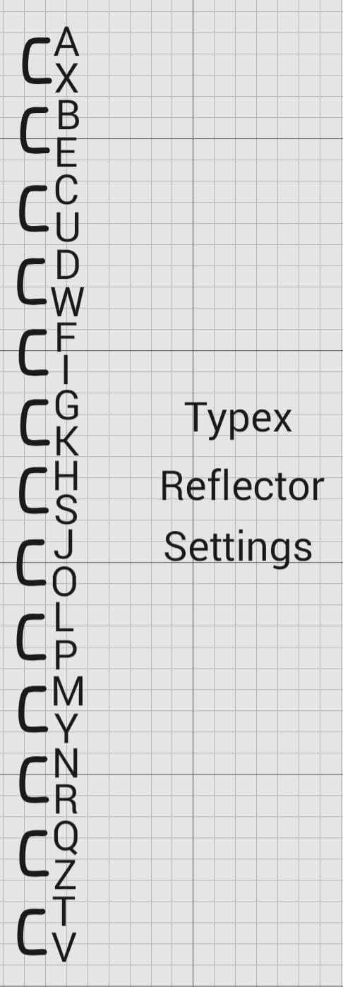
The official information on the Typex reflector is still classified, but the wiring deduced above was authorised as acceptable for release by Tony Comer, the former GCHQ historian.
The keyboard
Typex was built to handle not only letters, like Enigma, but also teleprinter traffic: the Typex Mark II is reported to have handled 300 characters a minute. It could send and print numbers and a few punctuation marks, but its Enigma-style encryption could only use the letters A–Z. So how was this done?
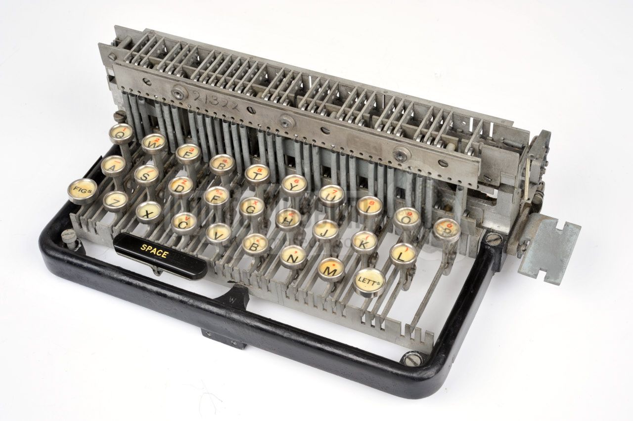
To switch between letters and figures, and to type a space, using only A–Z, a clever trick was used. Three of the least-used letters of the alphabet, Z, V and X, were used for switching to figures, switching back to letters, and space. Keys marked FIGS, LETTS and a space bar were provided, but had no switch wired beneath them: pressing one of these keys also pressed down the matching letter key through a linking bar, which activated that letter. So pressing FIGS also pushed the Z key down, and pressing space also pressed the X key. Once in figure shift, the printer carriage moved so that the figures and punctuation shown in red above each key were printed when the hammer fired.
So what happened when operators actually wanted to type Z, X or V? These letters were moved to shifted characters above the D, G and C keys. So to type the words TYPEX VARIES MAZE. you would press: T, Y, P, E, FIGS, G, LETTS, space, FIGS, C, LETTS, A, R, I, E, S, space, M, A, FIGS, D, LETTS, E, FIGS, M. The letters actually sent through the cipher rotors would be TYPEZGVXZCVARIESXMAZDVEZM. In cipher mode, this string is enciphered through the rotors and printed on the right-hand printer. When deciphering, the left-hand printer types the string of cipher letters, which are deciphered with the same rotor settings to get back the original string. When a deciphered Z is received, the second printer switches to figures; a V switches it back to letters; and an X moves it on a space.
When a key is pressed, an interlock bar is pushed out from the actuator, locking the key down and stopping any other key being pressed until both printers have finished and the actuator has completed a full turn. The key is then released, ready for the next key press.
The actuator
The actuator is a set of electrical and mechanical parts that control the sequence of events needed to encipher and print each character. Through an ingenious set of five solenoids and several cams, it steps the rotors and works the printers’ paper feed and figure/letter shift mechanisms.
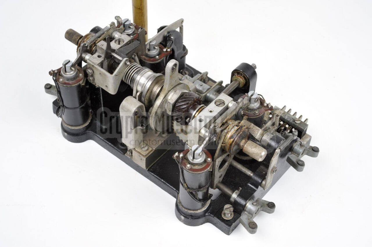
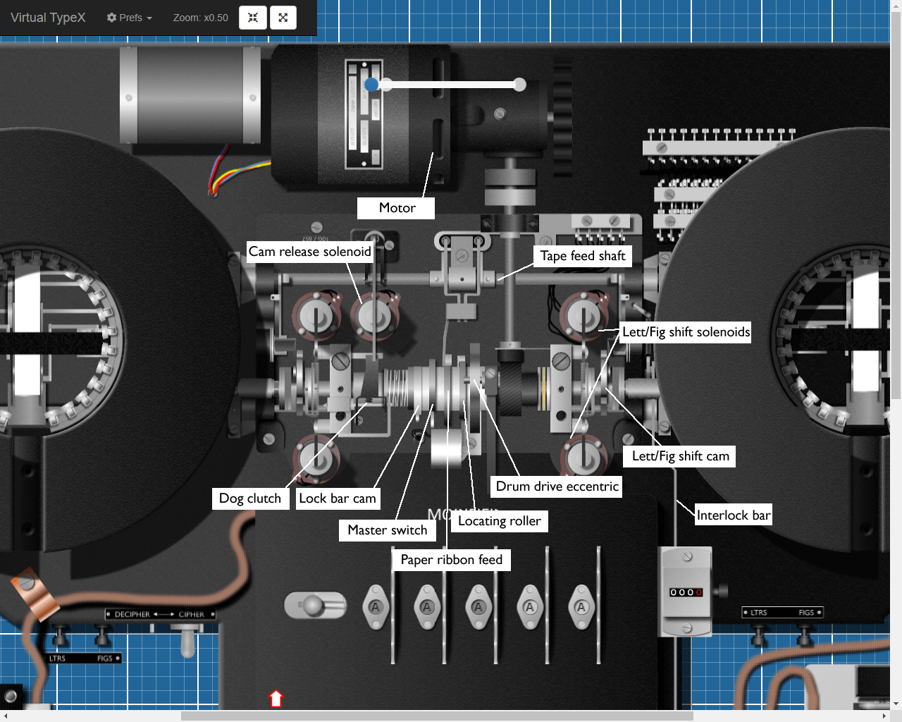
A motor drives the clutch system and shaft (shown in the middle of the diagram below), with the cams locked in place. When a key is pressed, the cam release solenoid pulls down, letting the dog clutch engage, which starts the main cam shaft turning.
First, the lock bar cam releases a lever, which moves the interlock bar, locking the pressed key down and stopping any other key being pressed. Next, the drum drive eccentric rises, pulling up the rotor pawl levers in the drum unit and stepping the rotors to their next position.
Next, the master switch cam pushes on a contact that completes the circuit through the keyboard, printers and rotors, so the printers type the current plain and cipher letters. Then the paper ribbon feed cam pushes up on a lever, joining it to the tape feed shaft at the back of the actuator. This releases the spring-loaded lever, turning the shaft backwards, and the motion is passed along to the paper feed on each printer through a shaft coupler.
Finally, as the main shaft completes a full turn, the dog clutch catches on the cam release solenoid lever again and disengages, while a slot on the locating roller leaves the cam shaft at a fixed point, ready for the next key press. The lock bar cam, returning to its starting position, releases the pressed key.
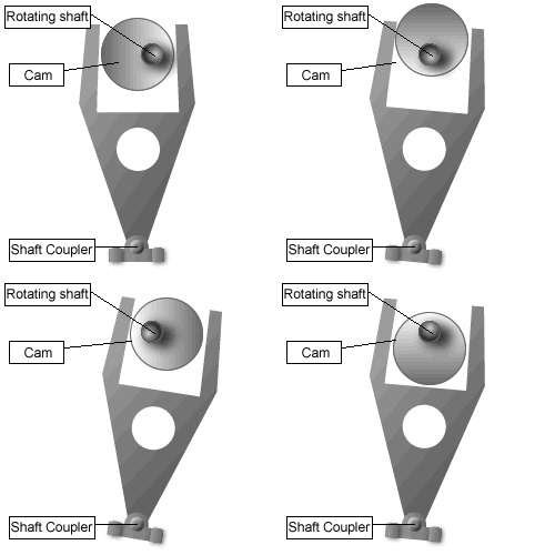
The actuator also controls the printers’ shift between letters and figures. Each printer has a pair of solenoids that release a clutch, if it is in the other mode, letting a shaft turn 180 degrees. This is connected to the letter/figure shift cam, which sits in a Y-shaped lever (see the animation): as the cam turns, it pushes the lever, which tilts the shaft coupler. The coupler is connected to the printer’s shift mechanism, setting the printer to the right mode.
The printers
On the Mark II, Mark 22 and Mark 23 Typex there is a printer on each side. The left one is the plain printer and the right one the cipher printer. They are identical, with coupler shafts on both sides, so one standard replaceable unit served for both.
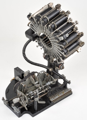
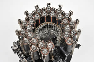
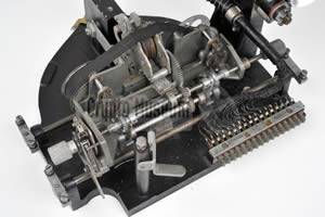
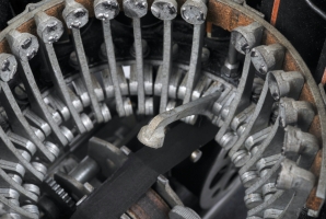
A ring of twenty-six solenoids is connected to levers arranged in a circle. For each letter, a solenoid pulls on a lever, making the print head strike through the ribbon onto the paper tape in the centre of the circle. The printer, while complex, allows an impressive typing speed of 300 characters a minute.
Each print head has two characters, and the shift mechanism moves the strike area so the second character on each head can strike instead. The shift mechanism is controlled through one of two shift coupler levers, one on each side of the printer. The other coupler controls the spacing mechanism that feeds the paper.
Manual override buttons in front of each printer let the operator set the printer to letters or figures by hand. This is useful for checking the printer is in letter mode before starting a new message, as the shift carriage may have been left in figure mode at the end of the last one.
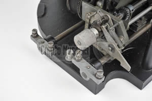
The paper tape can be fed by hand using a small knob sticking out near the centre on each side of the printer. This is also attached to a double feed-out cam, which automatically splits the cipher text into five-letter groups on the right printer. A geared shaft connected to the cipher/decipher lever on the front of the Typex disables the double feed-out cam on one printer at a time, so in cipher mode only the right-hand printer prints in five-letter groups, and in decipher mode only the left-hand one does.
The cipher/decipher lever also changes what the Z, X and V keys do: in decipher mode they type letters, otherwise they work the letter/figure shift and space. In cipher mode, the left-hand printer shifts the carriage or spaces when it receives Z, X or V, while the right-hand printer just prints the letters. In decipher mode, these are reversed.
Next: using Virtual Typex.